Universal 2 Series - Positive Displacement Pumps


Pumps / Positive Displacement Pumps
The Waukesha Universal 2 Series positive displacement pumps include advanced sanitation technologies, long life features and installation flexibility. Clean-in-Place (CIP) capable with optional flat body profile and free draining vertical ports. This highly robust pump can run at pressures of up to 500 psi.

Key Features & Benefits
- CIP capability available. Pump body has optional internal flat body profile and
will free drain with vertical ports. Optional rotor and body hub drilling provided
for difficult CIP cleaning applications. - Cover is free draining in horizontal or vertical port positions.
- Rotor/shaft connection sealed from product zone.
- Single mechanical seals standard. Optional double mechanical seals
also available. - Seal flush optional: seal areas interconnected to improve circulation
and draining of seal flush fluid. Steam-In-Place also is optional. - Stainless steel bearing frame optional on models 006 to 370.
- Aseptic design (Option)
Long-life Features
- Up to 500 psi (34.5 bar) pressure capability.
- Special rotor nut designed for extended service without loosening.
- No bearings in the product zone.
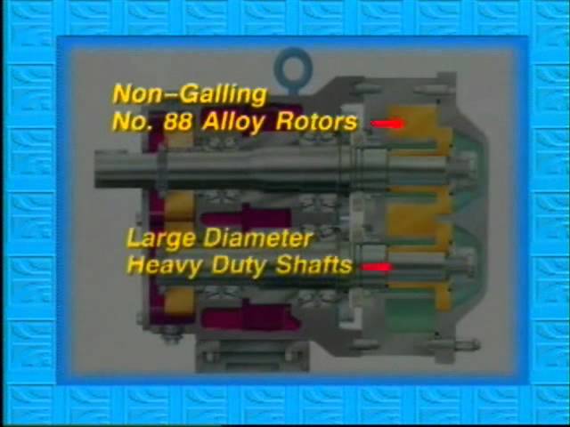
- Large diameter 17-4 PH shafts for greater strength and stiffness.
Helps reduce vibration; extends seal life. - Heavy duty bearing frame (stainless steel available as an option).
- Double tapered roller bearings.
- Greased lubed bearings for positive lubrication to all bearings over entire speed,
temperature and pressure range. - Body retaining screws for maintaining mechanical seal contact during inspection.
- Extended outer seal life. A wave spring, instead of an O-ring, mechanically loads
the seal. - O-Ring on inner seal, seals on clean surface as seal moves due to wear.
- Unique mechanical seal design utilizes 3 pin stationary seal and special
design shaft for rotary seal.
Time-tested Waukesha Cherry-Burrell® rotary pump; circumferential-piston operating principle
In the Waukesha Cherry-Burrell design, arc-shaped "pistons” (rotor wings) travel in annular-shaped cylinders machined in the pump body; the resulting long sealing path reduces slippage and produces a smooth flow of product without destructive pulses or pressure peaks and without valves or complex parts.


FOR LOW VISCOSITY FLUIDS
Rotors, made of Waukesha “88” alloy, can be run with close clearance to the 316L stainless steel fluid head, without galling or seizing should inadvertent pressure surges cause contact. The close clearances combined with the rotor geometry, which gives a long sealing path between the pump inlet and outlet, means low slip operation. As a result, you achieve: high efficiency, good priming ability, metering capability and good flow control.

FOR HIGH VISCOSITY FLUIDS
The large fluid cavities of the rotors plus the large, easy entry anti-cavitation ports, allow efficient pumping of high viscosity fluids, slurries or even liquids with large chunks or particles.


FOR NON-LUBRICATING AND ABRASIVE FLUIDS
The Waukesha Cherry-Burrell design has no bearings in the fluid being pumped, no sliding or rolling contact and no rotor-to-rotor contact. This produces EXCELLENT SERVICE LIFE even under severe operating conditions.


Food and Beverage
- Soups, Stews, Tomato Paste
- Vegetables, Dressings
- Chocolate, Fats & Oils
- Batters, Cream Fillings
- Brewery, Wort
- Soft/Fruit Drinks


Dairy
- Cream, Milk
- Cheese Curd & Whey
- Cottage Cheese
- Yogurt


Pharmaceutical/Cosmetics
- Pill Pastes
- Hand Sanitizers
- Syrups, Extracts, Slurries
- Face Creams & Lotions
- Lip Stick, Makeup, Hair Styling Gels & Liquids
- Dyes & Alcohols


Chemical/Industrial
- Solvents, Paints
- Fuels
- Resins, Polymers & Sludges
- Oil & Lubricants
- Soaps


MODEL 006-U2
0-1000 RPM speed range. 1" (25.4 mm) and 1½" (38.1 mm) port sizes available; suitable to 300 PSI (20.7 bar) differential pressure. Temperature range -40°F (-40°C) to 300°F (149°C).

|
|
A
|
AO
|
B
|
CP
|
CP1
|
CP4
|
D
|
E
|
F
|
G
|
I
|
J
|
L
|
O
|
U
|
X
|
2X
|
|---|---|---|---|---|---|---|---|---|---|---|---|---|---|---|---|---|---|
|
IN
|
4.75
|
8.3
|
3.75
|
11.71
|
13.92
|
14.92
|
5.50
|
1.94
|
2.31
|
.41slot
|
7.66
|
2.93
|
9.61
|
4.21
|
.875
|
3.49
|
6.97
|
|
MM
|
121
|
211
|
95
|
297
|
354
|
379
|
140
|
49
|
59
|
10 slot
|
194
|
74
|
244
|
107
|
22.23
|
89
|
177
|
CP= Standard Cover, CP1= Jacketed Cover, CP4= Manual Vented Cover, Connection sizes for Jacketed Covers are "-14 NPT on Models 006-U2 to 030-U2, 1"-11- NPT on Models 042-U2 to 220-U2.
Dimension 'X' and '2X' apply for Bevel Seat, "S"-Clamp, "Q"-Clamp, 15I and 14I fittings (except 320 U2).
Approximate shipping weight 56 lb. (25.4 kg.).
NOTES: Dimensions are for guidance purposes only. Contact your WCB Representative if more detailed measurements are needed. Waukesha Cherry-Burrell (WCB) curves are intended for use as an aid for preliminary selection of pumps by trained and qualified engineers. All selections must be reviewed by authorized WCB personnel prior to placing an order. WCB is not responsible for unauthorized or incorrect selections resulting from the use of these curves.
MODEL 015-U2
0-1000 RPM speed range. 1½" (38.1 mm) port sizes available; suitable to 250 PSI (17.2 bar) differential pressure. Temperature range -40°F (-40°C) to 300°F (149°C).
|
|
A
|
AO
|
B
|
CP
|
CP1
|
CP4
|
D
|
E
|
F
|
G
|
I
|
J
|
L
|
O
|
U
|
X
|
2X
|
|---|---|---|---|---|---|---|---|---|---|---|---|---|---|---|---|---|---|
|
IN
|
4.75
|
8.3
|
3.75
|
11.71
|
13.92
|
14.92
|
5.50
|
1.94
|
2.31
|
.41slot
|
7.66
|
2.93
|
9.61
|
4.21
|
.875
|
3.49
|
6.97
|
|
MM
|
121
|
211
|
95
|
297
|
354
|
379
|
140
|
49
|
59
|
10 slot
|
194
|
74
|
244
|
107
|
22.23
|
89
|
177
|
CP= Standard Cover, CP1= Jacketed Cover, CP4= Manual Vented Cover, Connection sizes for Jacketed Covers are ¾"-14 NPT on Models 006-U2 to 030-U2, 1"-11-½ NPT on Models 042-U2 to 220-U2.
Dimension 'X' and '2X' apply for Bevel Seat, "S"-Clamp, "Q"-Clamp, 15I and 14I fittings (except 320 U2).
Approximate shipping weight 56 lb. (25.4 kg.).
NOTES: Dimensions are for guidance purposes only. Contact your WCB Representative if more detailed measurements are needed. Waukesha Cherry-Burrell (WCB) curves are intended for use as an aid for preliminary selection of pumps by trained and qualified engineers. All selections must be reviewed by authorized WCB personnel prior to placing an order. WCB is not responsible for unauthorized or incorrect selections resulting from the use of these curves.
MODEL 018-U2
0-700 RPM speed range. 1½" (38.1 mm) and 2" (50.8 mm) port sizes available; suitable to 200 PSI (13.8 bar) differential pressure. Temperature range -40°F (-40°C) to 300°F (149°C).
|
|
A
|
AO
|
B
|
CP
|
CP1
|
CP4
|
D
|
E
|
F
|
G
|
I
|
J
|
L
|
O
|
U
|
X
|
2X
|
|---|---|---|---|---|---|---|---|---|---|---|---|---|---|---|---|---|---|
|
IN
|
4.75
|
8.3
|
3.75
|
12.37
|
14.59
|
15.58
|
5.50
|
1.94
|
2.31
|
.41slot
|
7.66
|
2.93
|
9.84
|
4.21
|
.875
|
3.49
|
6.97
|
|
MM
|
121
|
211
|
95
|
314
|
371
|
396
|
140
|
49
|
59
|
10 slot
|
194
|
74
|
250
|
107
|
22.23
|
89
|
177
|
CP= Standard Cover, CP1= Jacketed Cover, CP4= Manual Vented Cover, Connection sizes for Jacketed Covers are ¾"-14 NPT on Models 006-U2 to 030-U2, 1"-11-½ NPT on Models 042-U2 to 220-U2.
Dimension 'X' and '2X' apply for Bevel Seat, "S"-Clamp, "Q"-Clamp, 15I and 14I fittings (except 320 U2).
Approximate shipping weight 65 lb. (29.5 kg.).
NOTES: Dimensions are for guidance purposes only. Contact your WCB Representative if more detailed measurements are needed. Waukesha Cherry-Burrell (WCB) curves are intended for use as an aid for preliminary selection of pumps by trained and qualified engineers. All selections must be reviewed by authorized WCB personnel prior to placing an order. WCB is not responsible for unauthorized or incorrect selections resulting from the use of these curves.
MODEL 030-U2
0-600 RPM speed range. 1½" (38.1 mm) and 2" (50.8 mm) port sizes available; suitable to 250 PSI (17.2 bar) differential pressure. Temperature range -40°F (-40°C) to 300°F (149°C).
|
|
A
|
AO
|
B
|
CP
|
CP1
|
CP4
|
D
|
E
|
F
|
G
|
I
|
J
|
L
|
O
|
U
|
X
|
2X
|
|---|---|---|---|---|---|---|---|---|---|---|---|---|---|---|---|---|---|
|
IN
|
6.25
|
10.29
|
4.25
|
14.49
|
16.49
|
17.58
|
6.86
|
2.31
|
2.56
|
.41slot
|
8.83
|
3.56
|
11.61
|
5.21
|
1.25
|
4.25
|
8.5
|
|
MM
|
159
|
261
|
108
|
368
|
419
|
447
|
174
|
59
|
65
|
10 slot
|
224
|
90
|
295
|
132
|
31.75
|
108
|
216
|
CP= Standard Cover, CP1= Jacketed Cover, CP4= Manual Vented Cover, Connection sizes for Jacketed Covers are ¾"-14 NPT on Models 006-U2 to 030-U2, 1"-11-½ NPT on Models 042-U2 to 220-U2.
Dimension 'X' and '2X' apply for Bevel Seat, "S"-Clamp, "Q"-Clamp, 15I and 14I fittings (except 320 U2).
Approximate shipping weight 130 lb. (59.0 kg.).
NOTES: Dimensions are for guidance purposes only. Contact your WCB Representative if more detailed measurements are needed. Waukesha Cherry-Burrell (WCB) curves are intended for use as an aid for preliminary selection of pumps by trained and qualified engineers. All selections must be reviewed by authorized WCB personnel prior to placing an order. WCB is not responsible for unauthorized or incorrect selections resulting from the use of these curves.
MODEL 040-U2
0-600 RPM speed range. 2" (50.8 mm) port size available; suitable to 150 PSI (10 bar) differential pressure. Temperature range -40°F (-40°C) to 300°F (149°C).
|
|
A
|
AO
|
B
|
CP
|
CP1
|
CP4
|
D
|
E
|
F
|
G
|
I
|
J
|
L
|
O
|
U
|
X
|
2X
|
|---|---|---|---|---|---|---|---|---|---|---|---|---|---|---|---|---|---|
|
IN
|
6.25
|
10.29
|
4.25
|
14.87
|
16.87
|
17.96
|
6.86
|
2.31
|
2.56
|
.41slot
|
8.83
|
3.56
|
11.99
|
5.21
|
1.25
|
4.31
|
8.62
|
|
MM
|
159
|
261
|
108
|
378
|
428
|
456
|
174
|
59
|
65
|
10 slot
|
224
|
90
|
305
|
132
|
31.75
|
109
|
219
|
CP= Standard Cover, CP1= Jacketed Cover, CP4= Manual Vented Cover, Connection sizes for Jacketed Covers are ¾"-14 NPT on Models 006-U2 to 030-U2, 1"-11-½ NPT on Models 042-U2 to 220-U2.
Dimension 'X' and '2X' apply for Bevel Seat, "S"-Clamp, "Q"-Clamp, 15I and 14I fittings (except 320 U2).
Approximate shipping weight 140 lb. (64.0 kg.).
NOTES: Dimensions are for guidance purposes only. Contact your WCB Representative if more detailed measurements are needed. Waukesha Cherry-Burrell (WCB) curves are intended for use as an aid for preliminary selection of pumps by trained and qualified engineers. All selections must be reviewed by authorized WCB personnel prior to placing an order. WCB is not responsible for unauthorized or incorrect selections resulting from the use of these curves.
MODEL 045-U2
0-600 RPM speed range. 2" (50.8 mm) port sizes available; suitable to 450 PSI (31.0 bar) differential pressure. Temperature range -40°F (-40°C) to 300°F (149°C).
|
|
A
|
AO
|
B
|
CP
|
CP1
|
CP4
|
D
|
E
|
F
|
G
|
I
|
J
|
L
|
O
|
U
|
X
|
2X
|
|---|---|---|---|---|---|---|---|---|---|---|---|---|---|---|---|---|---|
|
IN
|
8.25
|
15.31
|
5.87
|
18.59
|
20.70
|
22.28
|
9.56
|
3.50
|
4.12
|
.53
|
10.99
|
5.06
|
14.86
|
7.31
|
1.625
|
5.37
|
10.75
|
|
MM
|
210
|
389
|
149
|
472
|
526
|
566
|
243
|
89
|
105
|
13
|
279
|
129
|
377
|
186
|
41.28
|
136
|
273
|
CP= Standard Cover, CP1= Jacketed Cover, CP4= Manual Vented Cover, Connection sizes for Jacketed Covers are ¾"-14 NPT on Models 006-U2 to 030-U2, 1"-11-½ NPT on Models 042-U2 to 220-U2.
Dimension 'X' and '2X' apply for Bevel Seat, "S"-Clamp, "Q"-Clamp, 15I and 14I fittings (except 320 U2).
Approximate shipping weight 295 lb. (134.0 kg.).
NOTES: Dimensions are for guidance purposes only. Contact your WCB Representative if more detailed measurements are needed. Waukesha Cherry-Burrell (WCB) curves are intended for use as an aid for preliminary selection of pumps by trained and qualified engineers. All selections must be reviewed by authorized WCB personnel prior to placing an order. WCB is not responsible for unauthorized or incorrect selections resulting from the use of these curves.
MODEL 060-U2
0-600 RPM speed range. 2½" (63.5 mm) port sizes available; suitable to 300 PSI (20.7 bar) differential pressure. Temperature range -40°F (-40°C) to 300°F (149°C).
|
|
A
|
AO
|
B
|
CP
|
CP1
|
CP4
|
D
|
E
|
F
|
G
|
I
|
J
|
L
|
O
|
U
|
X
|
2X
|
|---|---|---|---|---|---|---|---|---|---|---|---|---|---|---|---|---|---|
|
IN
|
8.25
|
15.31
|
5.87
|
19.14
|
21.25
|
22.83
|
9.56
|
3.50
|
4.12
|
.53
|
10.99
|
5.06
|
15.14
|
7.31
|
1.625
|
5.37
|
10.75
|
|
MM
|
210
|
389
|
149
|
486
|
540
|
580
|
243
|
89
|
105
|
13
|
279
|
129
|
385
|
186
|
41.28
|
136
|
273
|
CP= Standard Cover, CP1= Jacketed Cover, CP4= Manual Vented Cover, Connection sizes for Jacketed Covers are "-14 NPT on Models 006-U2 to 030-U2, 1"-11- NPT on Models 042-U2 to 220-U2.
Dimension 'X' and '2X' apply for Bevel Seat, "S"-Clamp, "Q"-Clamp, 15I and 14I fittings (except 320 U2).
Approximate shipping weight 285 lb. (129.3 kg.).
NOTES: Dimensions are for guidance purposes only. Contact your WCB Representative if more detailed measurements are needed. Waukesha Cherry-Burrell (WCB) curves are intended for use as an aid for preliminary selection of pumps by trained and qualified engineers. All selections must be reviewed by authorized WCB personnel prior to placing an order. WCB is not responsible for unauthorized or incorrect selections resulting from the use of these curves.
MODEL 130-U2
0-600 RPM speed range. 3" (76.2 mm) port sizes available; suitable to 200 PSI (13.8 bar) differential pressure. Temperature range -40°F (-40°C) to 300°F (149°C).
|
|
A
|
AO
|
B
|
CP
|
CP1
|
CP4
|
D
|
E
|
F
|
G
|
I
|
J
|
L
|
O
|
U
|
X
|
2X
|
|---|---|---|---|---|---|---|---|---|---|---|---|---|---|---|---|---|---|
|
IN
|
8.25
|
15.31
|
5.87
|
20.15
|
22.27
|
23.84
|
9.56
|
3.50
|
4.12
|
.53
|
10.99
|
5.06
|
15.77
|
7.31
|
1.625
|
5.37
|
10.75
|
|
MM
|
210
|
389
|
149
|
512
|
566
|
606
|
243
|
89
|
105
|
13
|
279
|
129
|
401
|
186
|
41.28
|
136
|
273
|
CP= Standard Cover, CP1= Jacketed Cover, CP4= Manual Vented Cover, Connection sizes for Jacketed Covers are ¾"-14 NPT on Models 006-U2 to 030-U2, 1"-11-½ NPT on Models 042-U2 to 220-U2.
Dimension 'X' and '2X' apply for Bevel Seat, "S"-Clamp, "Q"-Clamp, 15I and 14I fittings (except 320 U2).
Approximate shipping weight 305 lb. (138.3 kg.).
NOTES: Dimensions are for guidance purposes only. Contact your WCB Representative if more detailed measurements are needed. Waukesha Cherry-Burrell (WCB) curves are intended for use as an aid for preliminary selection of pumps by trained and qualified engineers. All selections must be reviewed by authorized WCB personnel prior to placing an order. WCB is not responsible for unauthorized or incorrect selections resulting from the use of these curves.
MODEL 180-U2
0-600 RPM speed range. 3" (76.2 mm) port sizes available; suitable to 450 PSI (31.0 bar) differential pressure. Temperature range -40°F (-40°C) to 300°F (149°C).
|
|
A
|
AO
|
B
|
CP
|
CP1
|
CP4
|
D
|
E
|
F
|
G
|
I
|
J
|
L
|
O
|
U
|
X
|
2X
|
|---|---|---|---|---|---|---|---|---|---|---|---|---|---|---|---|---|---|
|
IN
|
8.50
|
19.13
|
9.00
|
23.26
|
25.32
|
28.51
|
12.38
|
3.75
|
7.25
|
.53 slot
|
14.80
|
6.38
|
18.25
|
9.38
|
2.0
|
6.53
|
13.06
|
|
MM
|
216
|
486
|
2.29
|
591
|
643
|
724
|
314
|
95
|
184
|
13 slot
|
376
|
162
|
464
|
238
|
50.8
|
168
|
337
|
CP= Standard Cover, CP1= Jacketed Cover, CP4= Manual Vented Cover, Connection sizes for Jacketed Covers are ¾"-14 NPT on Models 006-U2 to 030-U2, 1"-11-½ NPT on Models 042-U2 to 220-U2.
Dimension 'X' and '2X' apply for Bevel Seat, "S"-Clamp, "Q"-Clamp, 15I and 14I fittings (except 320 U2).
Approximate shipping weight 520 lb. (236.0 kg.).
NOTES: Dimensions are for guidance purposes only. Contact your WCB Representative if more detailed measurements are needed. Waukesha Cherry-Burrell (WCB) curves are intended for use as an aid for preliminary selection of pumps by trained and qualified engineers. All selections must be reviewed by authorized WCB personnel prior to placing an order. WCB is not responsible for unauthorized or incorrect selections resulting from the use of these curves.
MODEL 210-U2
0-600 RPM speed range. 4" (101.6 mm) port sizes available; suitable to 500 PSI (34.5 bar) differential pressure. Temperature range -40°F (-40°C) to 300°F (149°C).
|
|
A
|
AO
|
B
|
CP
|
CP1
|
CP4
|
D
|
E
|
F
|
G
|
I
|
J
|
L
|
O
|
U
|
X
|
2X
|
|---|---|---|---|---|---|---|---|---|---|---|---|---|---|---|---|---|---|
|
IN
|
12.00
|
22.38
|
11.63
|
27.08
|
28.58
|
--
|
13.88
|
5.25
|
8.00
|
.66
|
17.80
|
6.88
|
21.24
|
10.38
|
2.375
|
7.37
|
14.73
|
|
MM
|
305
|
568
|
295
|
688
|
726
|
--
|
353
|
133
|
203
|
17
|
452
|
175
|
539
|
264
|
60.45
|
187
|
374
|
CP= Standard Cover, CP1= Jacketed Cover, CP4= Manual Vented Cover, Connection sizes for Jacketed Covers are ¾"-14 NPT on Models 006-U2 to 030-U2, 1"-11-½ NPT on Models 042-U2 to 220-U2.
Dimension 'X' and '2X' apply for Bevel Seat, "S"-Clamp, "Q"-Clamp, 15I and 14I fittings (except 320 U2).
Approximate shipping weight 915 lb. (415.0 kg.).
NOTES: Dimensions are for guidance purposes only. Contact your WCB Representative if more detailed measurements are needed. Waukesha Cherry-Burrell (WCB) curves are intended for use as an aid for preliminary selection of pumps by trained and qualified engineers. All selections must be reviewed by authorized WCB personnel prior to placing an order. WCB is not responsible for unauthorized or incorrect selections resulting from the use of these curves.
MODEL 213-U2
0-600 RPM speed range. 4" (101.6 mm) port sizes available; suitable to 500 PSI (34.5 bar) differential pressure. Temperature range -40°F (-40°C) to 300°F (149°C).
|
|
A
|
AO
|
B
|
CP
|
CP1
|
CP4
|
D
|
E
|
F
|
G
|
I
|
J
|
L
|
O
|
U
|
X
|
2X
|
|---|---|---|---|---|---|---|---|---|---|---|---|---|---|---|---|---|---|
|
IN
|
12.00
|
22.38
|
11.63
|
27.08
|
-
|
-
|
13.88
|
5.25
|
8.00
|
.66
|
17.80
|
6.88
|
21.24
|
10.38
|
2.375
|
8.62
|
17.25
|
|
MM
|
305
|
568
|
295
|
688
|
-
|
-
|
353
|
133
|
203
|
17
|
425
|
175
|
539
|
264
|
60.45
|
219
|
438
|
CP= Standard Cover, CP1= Jacketed Cover, CP4= Manual Vented Cover, Connection sizes for Jacketed Covers are ¾"-14 NPT on Models 006-U2 to 030-U2, 1"-11-½ NPT on Models 042-U2 to 220-U2.
Dimension 'X' and '2X' apply for Bevel Seat, "S"-Clamp, "Q"-Clamp, 15I and 14I fittings (except 320 U2).
Approximate shipping weight 915 lb. (415.0 kg.).
NOTES: Dimensions are for guidance purposes only. Contact your WCB Representative if more detailed measurements are needed. Waukesha Cherry-Burrell (WCB) curves are intended for use as an aid for preliminary selection of pumps by trained and qualified engineers. All selections must be reviewed by authorized WCB personnel prior to placing an order. WCB is not responsible for unauthorized or incorrect selections resulting from the use of these curves.
MODEL 220-U2
0-600 RPM speed range. 4" (101.6 mm) port sizes available; suitable to 300 PSI (20.7 bar) differential pressure. Temperature range -40°F (-40°C) to 300°F (149°C).
|
|
A
|
AO
|
B
|
CP
|
CP1
|
CP4
|
D
|
E
|
F
|
G
|
I
|
J
|
L
|
O
|
U
|
X
|
2X
|
|---|---|---|---|---|---|---|---|---|---|---|---|---|---|---|---|---|---|
|
IN
|
8.50
|
19.13
|
9.00
|
24.00
|
26.06
|
29.25
|
12.38
|
3.75
|
7.25
|
.53 slot
|
14.80
|
6.38
|
18.49
|
9.38
|
2.000
|
6.63
|
13.25
|
|
MM
|
216
|
486
|
229
|
610
|
662
|
743
|
314
|
95
|
184
|
13 slot
|
376
|
162
|
470
|
238
|
50.80
|
168
|
337
|
CP= Standard Cover, CP1= Jacketed Cover, CP4= Manual Vented Cover, Connection sizes for Jacketed Covers are ¾"-14 NPT on Models 006-U2 to 030-U2, 1"-11-½ NPT on Models 042-U2 to 220-U2.
Dimension 'X' and '2X' apply for Bevel Seat, "S"-Clamp, "Q"-Clamp, 15I and 14I fittings (except 320 U2).
Approximate shipping weight 590 lb. (268.0 kg.).
NOTES: Dimensions are for guidance purposes only. Contact your WCB Representative if more detailed measurements are needed. Waukesha Cherry-Burrell (WCB) curves are intended for use as an aid for preliminary selection of pumps by trained and qualified engineers. All selections must be reviewed by authorized WCB personnel prior to placing an order. WCB is not responsible for unauthorized or incorrect selections resulting from the use of these curves.
MODEL 320-U2
0-600 RPM speed range. 6" (152.4 mm) port sizes available; suitable to 300 PSI (20.7 bar) differential pressure. Temperature range -40°F (-40°C) to 300°F (149°C).
|
|
A
|
AO
|
B
|
CP
|
CP1
|
CP4
|
D
|
E
|
F
|
G
|
I
|
J
|
L
|
O
|
U
|
X
|
2X
|
|---|---|---|---|---|---|---|---|---|---|---|---|---|---|---|---|---|---|
|
IN
|
12.00
|
22.38
|
11.63
|
27.66
|
29.16
|
--
|
13.88
|
5.25
|
8.00
|
.66
|
17.80
|
6.88
|
21.63
|
10.38
|
2.375
|
8.00
|
16.00
|
|
MM
|
305
|
568
|
295
|
703
|
741
|
--
|
358
|
133
|
203
|
17
|
452
|
175
|
549
|
264
|
60.45
|
203
|
406
|
CP= Standard Cover, CP1= Jacketed Cover, CP4= Manual Vented Cover, Connection sizes for Jacketed Covers are ¾"-14 NPT on Models 006-U2 to 030-U2, 1"-11-½ NPT on Models 042-U2 to 220-U2.
Dimension 'X' and '2X' apply for Bevel Seat, "S"-Clamp, "Q"-Clamp, 15I and 14I fittings (except 320 U2).
Approximate shipping weight 895 lb. (406.0 kg.).
NOTES: Dimensions are for guidance purposes only. Contact your WCB Representative if more detailed measurements are needed. Waukesha Cherry-Burrell (WCB) curves are intended for use as an aid for preliminary selection of pumps by trained and qualified engineers. All selections must be reviewed by authorized WCB personnel prior to placing an order. WCB is not responsible for unauthorized or incorrect selections resulting from the use of these curves.
MODEL 370-U2
0-600 RPM speed range. 6" (152.4 mm) port sizes available; suitable to 200 PSI (13.8 bar) differential pressure. Temperature range -40°F (-40°C) to 300°F (149°C).
|
|
A
|
AO
|
B
|
CP
|
CP1
|
D
|
E
|
F
|
G
|
I
|
J
|
L
|
O
|
U
|
X
|
2X
|
|---|---|---|---|---|---|---|---|---|---|---|---|---|---|---|---|---|
|
IN
|
12.00
|
22.38
|
11.63
|
29.16
|
30.66
|
13.88
|
5.25
|
8.00
|
.66
|
17.80
|
6.88
|
22.32
|
10.38
|
2.38
|
8.50
|
17.00
|
|
MM
|
305
|
568
|
295
|
741
|
779
|
353
|
133
|
203
|
17
|
452
|
175
|
567
|
264
|
60.5
|
216
|
432
|
CP= Standard Cover, CP1= Jacketed Cover, CP4= Manual Vented Cover, Connection sizes for Jacketed Covers are ¾"-14 NPT on Models 006-U2 to 030-U2, 1"-11-½ NPT on Models 042-U2 to 220-U2.
Dimension 'X' and '2X' apply for Bevel Seat, "S"-Clamp, "Q"-Clamp, 15I and 14I fittings (except 320 U2).
Approximate shipping weight 945 lb. (428.6 kg.)
NOTES: Dimensions are for guidance purposes only. Contact your WCB Representative if more detailed measurements are needed. Waukesha Cherry-Burrell (WCB) curves are intended for use as an aid for preliminary selection of pumps by trained and qualified engineers. All selections must be reviewed by authorized WCB personnel prior to placing an order. WCB is not responsible for unauthorized or incorrect selections resulting from the use of these curves.
Click on the links below to download pump model performance curves for Universal 2 Series Positive Displacement pumps.
- Universal 2 Series - Model 006 - Performance Curve - 95-07075 || PDF
- Universal 2 Series - Model 015 - Performance Curve - 95-07076 || PDF
-
Universal 2 Series - Model 018 - Performance Curve - 95-07077 || PDF
-
Universal 2 Series - Model 030 - Performance Curve - 95-07078 || PDF
- Universal 2 Series - Model 040 - Performance Curve - 95-07241 || PDF
- Universal 2 Series - Model 045 - Performance Curve - 95-07106 || PDF
- Universal 2 Series - Model 060 - Performance Curve - 95-07079 || PDF
- Universal 2 Series - Model 130 - Performance Curve - 95-07080 || PDF
- Universal 2 Series - Model 180 - Performance Curve - 95-07107 || PDF
- Universal 2 Series - Model 210/213 - Performance Curve - 95-07156 || PDF
- Universal 2 Series - Model 220 - Performance Curve - 95-07081 || PDF
- Universal 2 Series - Model 320 - Performance Curve - 95-07132 || PDF
- Universal 2 Series - Model 370 - Performance Curve - 95-07245 || PDF